

 en
en  English
 Español
 عربى
عربى
When a new thermoforming mold design reaches the production floor, the first indication of trouble is often uneven wall thickness. The corners may be too thin, the part may warp as it cools, or the sheet may not pull into the deepest cavity. These failures are rarely random. They trace back to a small set of design decisions: draw ratio, draft angle, venting, cooling, and material behavior.
The good news is that these rules are learnable and testable. A mold that follows them can be brought into production faster and with far fewer adjustment cycles. This guide explains the design parameters that matter most, and shows how they influence actual packaging parts like cup lids, beverage cups, and lunch boxes.
The Core Formula Every Thermoforming Mold Design Starts With
The first number to calculate in any thermoforming mold design is the draw ratio. It predicts how much the plastic sheet will stretch and where the material will become thin. In practical terms, the draw ratio for a cylindrical cup is the part height divided by the opening diameter. A deeper or narrower cup will have a higher draw ratio, which forces the designer to add a plug assist or choose a thicker starting sheet.
A simple example makes this concrete: a milk tea cup with a 90 mm height and a 60 mm diameter has a draw ratio of 1.5. This is already a demanding geometry for vacuum forming alone. Adding a plug assist or switching to pressure forming helps distribute the material more evenly. The same geometry if designed without a proper draw ratio estimate can produce side walls that vary by more than 30% in thickness, which is unacceptable for beverage packaging.
Draw Ratio and Part Geometry: How to Keep Wall Thickness in Control
Before committing to a mold material or cutting tool, calculate the draw ratio for every feature on the part. The formula is simpler than it sounds: for a cup, divide the vertical depth by the average diameter. For a rectangular tray, use the depth divided by the smaller horizontal dimension.
| Draw Ratio | Recommended Process | Expected Wall Variation |
|---|---|---|
| Below 0.5 | Vacuum forming | Low |
| 0.5 to 1.0 | Vacuum with plug assist | Moderate |
| 1.0 to 1.5 | Pressure forming | Tighter |
| Above 1.5 | Special tooling or multi-stage | High risk |
This table is a starting point, not an absolute law. Some materials can stretch further than others. HIPS and PP handle deep draws better than PET, while PET needs very controlled temperature and mold cooling. The key is to set a realistic draw ratio before you start the CAD work, because it decides the sheet thickness and the number of forming stations.
Draft Angles, Corner Radii, and Undercuts: The Rules That Make Parts Release Easily
Once the sheet has been formed, the part must come out of the mold. This is where draft angle and corner radius play their role. A minimum draft angle of 1 degree is usually enough for shallow parts, but deeper cavities need 2 to 3 degrees to keep friction low and prevent scratches on the finished surface.
| Part Feature | Minimum Draft Angle | Minimum Radius |
|---|---|---|
| Shallow tray (depth under 25 mm) | 1 degree | 2x material thickness |
| Deep cup or lid (depth over 50 mm) | 2 to 3 degrees | 3x material thickness |
| Gender or hinge area | 3 degrees | 4x material thickness |
Undercuts complicate matters. In vacuum forming, a small undercut can often be stripped from an aluminum mold because the aluminum still has some flexibility. In pressure forming, undercuts are actually easier to support because the pressure holds the sheet against the mold. But large negative angles will force a collapsible mold or a separate side-acting mechanism, which adds cost. If you are designing a paper bowl lid with a curled edge, keep the undercut shallow and specify a polished tool surface. A proven paper bowl lid thermoforming mold relies on this kind of controlled geometry to release cleanly every cycle.
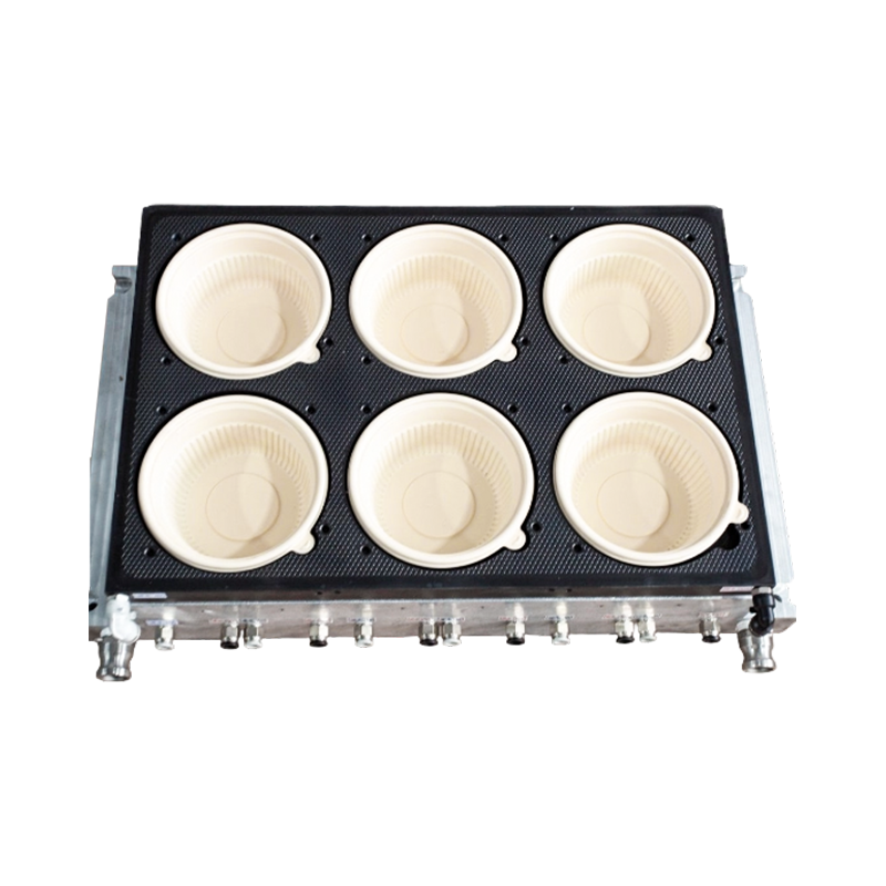
 Thermoforming Mold for Paper Bowl Lids with Precision CoolingThis mold is designed for paper bowl lids, using CNC and EDM machining for tight sealing. Its CFD-optimized cooling channels shorten cycles, while nitrided steel ensures durability in high-volume production.View Product →
How Material Choice Changes Thermoforming Mold Design
Material selection is not just a supply chain question. It directly affects cooling channel layout, venting size, and shrink allowance. Polypropylene (PP) needs generous venting because it retains heat and has a relatively high shrinkage rate. Polyethylene terephthalate (PET) is more heat-sensitive; it requires a hotter mold surface and precise cooling to avoid crystallinity pockets. Polystyrene (PS) is easy to form but brittle in sharp corners.
For a beverage lid that must seal tightly, the mold designer must consider the lid material's flexural modulus. The milk tea cup lid thermoforming mold used in high-speed production is engineered around the specific stretch behavior of PP or PET lids. The vent holes are placed at the deepest part of the cavity, and the cooling channels are sized to match the cycle target.
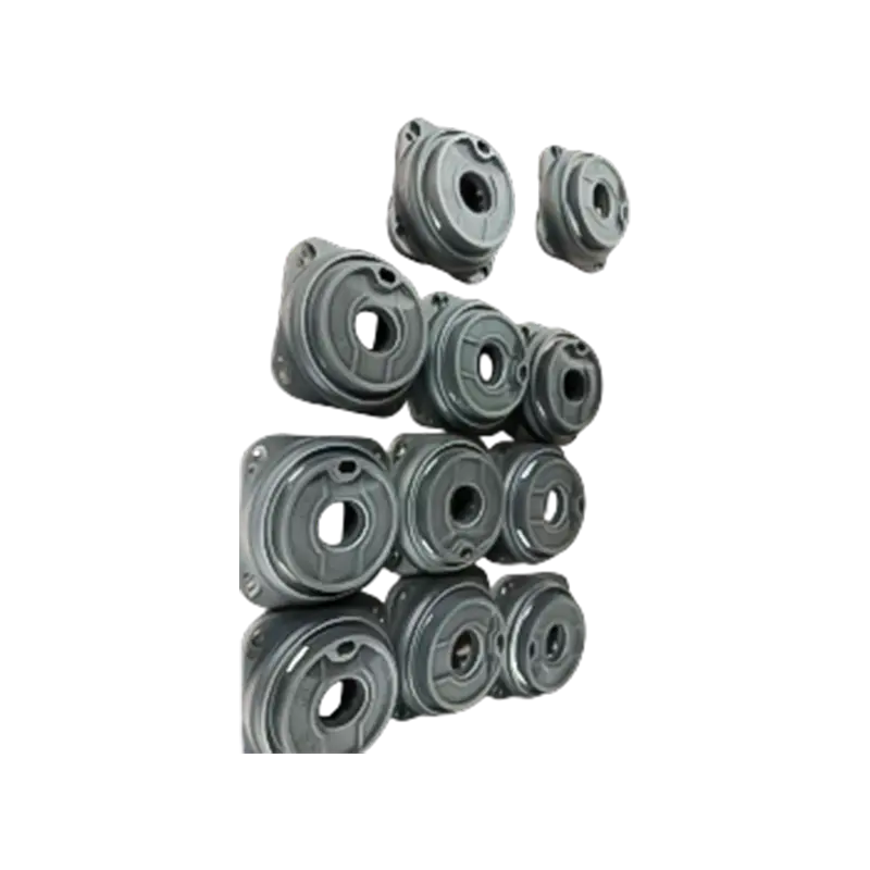 High-Speed Thermoforming Mold for Milk Tea Cup LidsTailored for milk tea lids, this mold works with PP, PET, PS, and PLA sheets. It features precise temperature control and a modular design, enabling efficient production with tight seals and smooth edges.View Product →
A common rule for many packaging materials is the 10-10-5 rule: a 10 mm draft angle, 10% shrink allowance for some PP grades, and 5 mm minimum radius for difficult draw areas. This rule is not universal, but it gives a quick sanity check for a new mold. For more detail, you can see how thermoforming mold design determines packaging performance and cost.
Cooling, Venting, and Trim: The Hidden Cost Drivers in Mold Design
Cycle time is the number that most directly determines unit cost. A well-designed cooling system can shave seconds off every cycle, and on a multi-cavity mold those seconds multiply rapidly. Cooling channels must be placed as close to the forming surface as possible without compromising tool strength. For a round lidded packaging box, the heat load is concentrated in the deepest corners, so the mold should have dedicated cooling loops there.
Venting is just as important. Air trapped between the sheet and the mold creates a bubble or a surface defect. Vent holes need to be placed in the areas where air gets trapped last, often at the deepest draw point. A common practice is to use a venting drill with a diameter between 0.5 mm and 1.0 mm, spaced carefully to avoid leaving visible marks on the part.
For a round lidded packaging box thermoforming mold that produces thousands of containers per shift, the trim system is equally critical. Steel rule dies are faster to build, while matched metal dies give cleaner edges and longer tool life. The choice should be made during the mold design phase, not after the machine is installed.
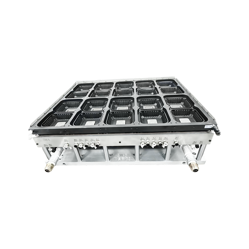 Round Lidded Packaging Box Thermoforming Mold with Multi-Cavity DesignThis mold produces round one-piece boxes with lids, compatible with PET, PP, PS, and PVC. Its multi-cavity structure and uniform heating ensure consistent dimensions and smooth surfaces for food packaging.View Product →
Common Thermoforming Mold Design Mistakes and How to Avoid Them
Even experienced designers repeat a few avoidable errors. Here are the most frequent ones:
- Ignoring the draw ratio until after the sheet thickness is fixed. This forces long setup loops on the machine.
- Using a draft angle that is too small for a deep cavity, which leads to part scratches or even stuck parts.
- Placing vent holes too far from the deepest point, leaving bubbles or incomplete detail.
- Copying a cooling design from a different part without recalculating the heat load.
- Forgetting to add shrink allowance for PP and PET, resulting in dimension drift after the first cooling cycle.
Each of these failures ties back to mold geometry and process conditions. Reviewing a mold design against a checklist of these items before machining can save days of trial and error. When you work with a mold maker that has CNC machining and a dedicated sampling former, you can test the design before mass production. That experience directly improves the first-run success rate.
FAQs About Thermoforming Mold Design
Q1: What is the minimum draft angle for a thermoforming mold?
For shallow parts, 1 degree is usually enough. For deep cavities over 50 mm, use 2 to 3 degrees. The material matters as well; PP and HIPS can tolerate lower draft angles than PET, which is more rigid.
Q2: How do I calculate the draw ratio for a cup?
Divide the cup height by the opening diameter. For example, a 90 mm tall cup with a 60 mm diameter has a draw ratio of 1.5. This means you should consider plug assist or pressure forming to control wall thickness.
Q3: What is the 10-10-5 rule in thermoforming mold design?
It is a quick starting reference: 10 degrees of draft angle for difficult materials, 10% shrink allowance for some polypropylenes, and 5 mm minimum radius for deep draw areas. Always verify the values for your specific material and part geometry.
Q4: How much shrink allowance should I add for PP and PET?
Polypropylene often needs around 1.5% to 2.5% shrink allowance, while PET can be closer to 0.5% to 1.0%. The exact number depends on the mold temperature, wall thickness, and the original material supplier's data sheet.
Start With the Part, Then Build the Mold
A successful thermoforming mold design is not a finished drawing; it is a decision record that shows how the part will stretch, how it will cool, and how it will be trimmed. The best mold makers discuss these choices with the packaging designer before any tool steel is cut.
By calculating draw ratio, setting a realistic draft angle, designing the venting and cooling around the geometry, and choosing a material-compatible process, you turn a risky mold into a predictable production asset. That is the difference between a mold that simply exists and a mold that delivers a consistent, profitable part.