

 en
en  English
 Español
 عربى
عربى
Why Mold Design Is the Real Variable Behind Thermoforming Results
Plastic thermoforming looks simple from the outside: a heated sheet is draped or pushed into a cavity, cooled, and trimmed. In practice, the mold is what decides whether the finished part holds tight tolerances, seals correctly, and survives a production run without rework. Two identical machines running the same sheet grade can produce very different scrap rates purely because of differences in vent layout, draft angle, or cooling channel spacing inside the tool. This is why thermoformed plastic packaging producers spend far more engineering time on tooling than on the forming machine itself.
This guide walks through the mechanics of the process, the design decisions that separate a workable mold from a problematic one, and the practical criteria buyers use when sourcing tooling for lunch boxes, cup lids, beverage cups, and clamshell trays.
A mold with poorly placed vent holes can add 15 to 25 percent to cycle time because the sheet cannot evacuate trapped air fast enough to form crisp corners, forcing operators to slow the cycle to avoid webbing defects.
The Thermoforming Process: What Actually Happens Inside the Mold
Plastic thermoforming converts a flat extruded sheet into a three-dimensional part using heat, pressure differential, and a shaped tool. The sequence is consistent across most thin-gauge applications, though the forming method varies by part geometry.
- The plastic sheet is clamped in a frame and indexed into a heating station, typically using ceramic or quartz heaters.
- Once the sheet reaches its forming temperature window, it is transferred over the open mold.
- Vacuum, air pressure, or a mechanical plug forces the softened sheet against the mold surface.
- Cooling channels inside the tool remove heat quickly so the part retains its shape when released.
- The formed sheet is trimmed, either in-mold or on a separate trim press, separating individual parts from the web.
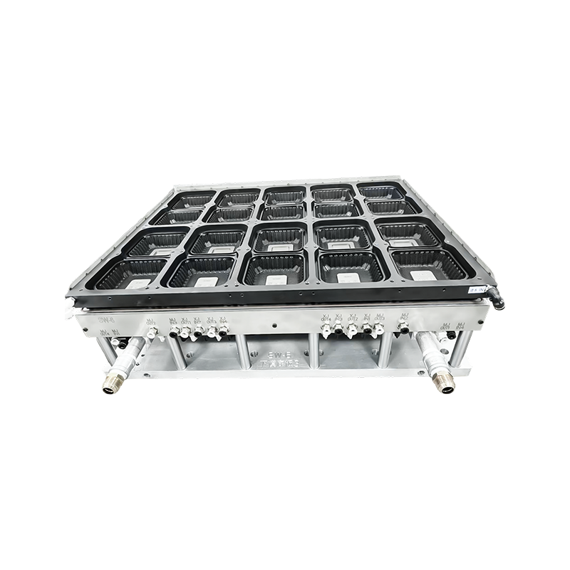
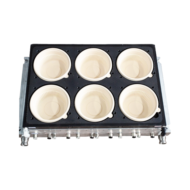
The mold surface itself is usually machined aluminum, chosen for its thermal conductivity rather than hardness. Aluminum pulls heat out of the formed plastic far faster than steel, which shortens cycle time and is one of the main reasons thermoforming tooling differs so much from injection molds.
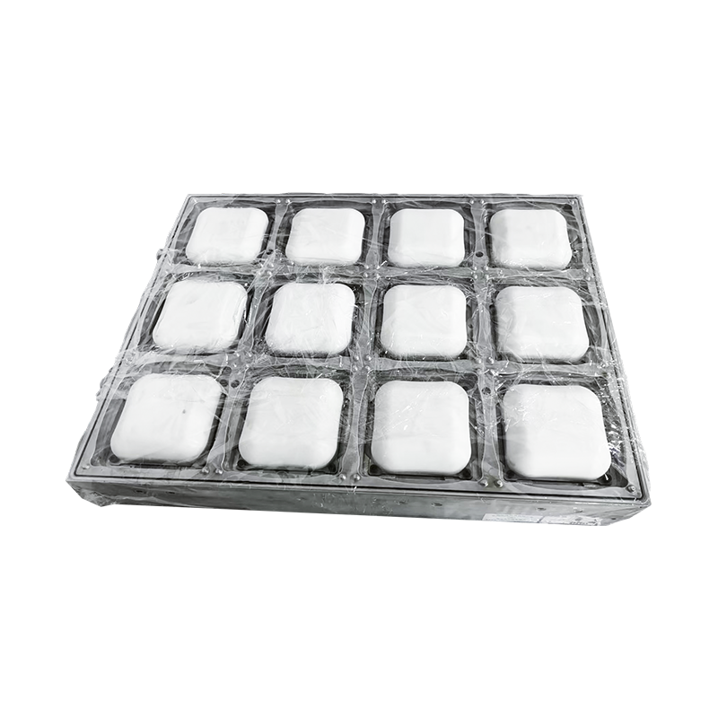
Aluminum tooling used for a Rectangular Clamshell Packaging Box Thermoforming Mold, showing the machined cavity and vent layout typical of thin-gauge food packaging tools.
Core Mold Design Elements That Affect Part Quality
Several design variables repeat across every thermoforming mold discussion, and each has a measurable effect on the finished part.
Draft Angle
Draft angle allows the formed part to release from the mold without tearing or scuffing. Shallow parts such as flat lids can use as little as 1 to 2 degrees, while deep-draw items like tall cups usually need 3 to 5 degrees on the mold walls to avoid drag marks.
Vent Hole Placement and Size
Vent holes let trapped air escape as the sheet contacts the mold surface. Holes are typically 0.3 to 0.8 millimeters in diameter, placed in corners and detail areas where air pockets form first. Too few vents leave rounded corners instead of sharp ones; too many weaken the cavity surface and can leave visible marks on the part.
Cooling Channel Layout
Water channels drilled or cast into the mold body pull heat away from the plastic. Uneven channel spacing creates hot spots that warp thin walls after demolding, which is one of the most common causes of parts that look correct off the tool but distort within a few hours.
Shrinkage Allowance
Different resins shrink at different rates as they cool. Polypropylene shrinks more than PET, so a mold cut for one resin family will not hold dimensions if the material is switched without adjusting the cavity size.
| Design Element | Typical Range | Effect if Incorrect |
|---|---|---|
| Draft Angle | 1 to 5 degrees | Part sticks or scuffs on release |
| Vent Hole Diameter | 0.3 to 0.8 mm | Rounded corners or webbing |
| Wall Thickness Ratio | 0.15 to 0.4 mm typical for thin wall | Weak spots or excess material use |
| Cooling Channel Spacing | 15 to 25 mm from cavity surface | Warping and cycle time inflation |
Thin-Wall Thermoforming: Where Most of the Difficulty Lives
Thin-wall thermoforming refers to parts formed from sheet under roughly 0.5 millimeters, common in lids, trays, and disposable cups. The challenge is that thinner material cools and stretches unevenly, so the mold has to compensate for physics the sheet itself cannot handle on its own.
Wall thinning is the central issue. As the sheet stretches into a cavity, material moving into deep or distant corners of the mold thins out more than material near the clamp frame. A poorly designed cavity can leave a corner at 60 percent of the nominal sheet thickness, which becomes the weakest point of the finished container. Mold designers address this with several techniques:
- Adjusting cavity geometry to reduce draw ratio in the deepest sections
- Using a plug assist to pre-stretch the sheet before vacuum takes over
- Sequencing vacuum zones so material is pulled progressively rather than all at once
- Controlling sheet temperature profile so the center of the sheet is slightly cooler than the edges before forming begins
For high-volume thin-wall production, even a 5 percent improvement in material distribution can translate into meaningful resin savings across a full production run, since thin-wall packaging is typically priced and specified by weight per part.
Plug Assist Thermoforming: When It Is Worth the Added Complexity
Plug assist thermoforming adds a mechanical plug that pushes into the sheet before vacuum is applied, pre-stretching the material so it distributes more evenly once it contacts the mold surface. It is not needed for every part, but it becomes important once draw depth exceeds roughly 1.5 times the part's smaller plan dimension.
Plug material and shape matter as much as timing. A plug that is too hot drags material and creates local thin spots at the point of first contact, while one that is too cold chills the sheet prematurely and can cause webbing. Plug assist tooling is typically specified with a temperature-controlled plug and a shape that mirrors roughly 70 to 85 percent of the cavity volume, leaving vacuum to complete the final detail.
Matching Mold Type to Packaging Application
Different packaging formats call for different tooling approaches, and it helps to compare them directly rather than treat thermoforming mold design as one uniform category.
| Application | Typical Depth | Common Forming Method | Key Design Priority |
|---|---|---|---|
| Lunch Box Thermoforming Mold | Moderate, multi-cavity trays | Vacuum with plug assist | Compartment wall consistency |
| Cup Lid Thermoforming Mold | Shallow, flat profile | Vacuum forming | Seal ring flatness and fit |
| Cup Thermoforming Mold | Deep draw, round profile | Plug assist vacuum | Even wall distribution and rim strength |
| Rectangular Clamshell Tray | Hinged, two-cavity form | Vacuum with matched hinge alignment | Hinge durability and closure fit |
Lid tooling and container tooling for the same product line are often designed together, since the two mating surfaces need to seal reliably across a full production tolerance range, not just when measured individually on a bench.
Material Selection for Thermoformed Plastic Packaging
Resin choice affects mold design almost as much as part geometry does, because shrinkage, forming temperature, and stiffness all vary by material family.
- PET: clear, stiff, favored for retail visibility packaging; forms at a narrower temperature window, which requires tighter heater zone control
- PP: better chemical and heat resistance, common for hot-fill or microwaveable containers; higher shrinkage than PET, so cavity dimensions must account for it
- PS: low cost and easy to form, but more brittle, often used for lids and trays that do not need high impact resistance
- PLA and other bio-based resins: increasingly specified for compostable packaging; typically forms at lower temperatures and can be more sensitive to cooling rate uniformity
Because shrinkage rates differ, a mold built for one resin family frequently cannot be swapped to another without dimensional adjustment. Buyers planning to run multiple materials on the same tool should specify this at the design stage rather than after the mold is cut.
Evaluating a Food Container Mold Manufacturer
Sourcing custom plastic packaging molds for food contact applications involves more than comparing tool price. A few criteria consistently separate reliable suppliers from ones that create downstream production problems.
| Criteria | What to Verify |
|---|---|
| Machining tolerance | Cavity dimensions held within stated tolerance across the full tool, not just at sample points |
| Material traceability | Aluminum grade and cooling channel design documented for the buyer's file |
| Trial run data | Sample parts measured for wall thickness distribution before full approval |
| Food contact compliance | Surface finish and design suitable for the intended resin and application |
| Post-sale support | Ability to modify vent layout or cooling channels if defects appear in production |
Requesting a first-article sample formed on the actual tool, rather than relying only on a machining report, remains the most reliable way to confirm that a mold will perform once it reaches production speed.
Custom Mold Design Workflow, Start to Finish
A typical custom tool moves through part review, cavity layout, machining, and trial forming before final approval. The trial stage is where most adjustments happen, usually to vent placement or cooling balance, since these are difficult to predict with full accuracy from drawings alone. Building in time for at least one trial iteration before locking a production schedule avoids rushed changes later.
Common Defects and Their Root Causes
| Defect | Likely Cause | Typical Fix |
|---|---|---|
| Webbing in corners | Insufficient venting or excess sheet sag before forming | Add vent holes, adjust heater profile |
| Thin or torn walls | Draw ratio too high for wall thickness | Add plug assist or revise geometry |
| Warping after cooling | Uneven cooling channel spacing | Rebalance channel layout |
| Poor lid to container fit | Mismatched shrinkage between mating tools | Adjust cavity dimensions to match resin shrinkage |
| Surface haze or drag marks | Insufficient draft angle | Increase draft on cavity walls |
Frequently Asked Questions
Q1: What is the difference between vacuum forming and plug assist thermoforming?
Vacuum forming relies only on air pressure difference to pull the sheet against the mold, while plug assist thermoforming uses a mechanical plug to pre-stretch the sheet first. Plug assist is generally used for deeper or more detailed parts where vacuum alone would leave uneven wall thickness.
Q2: How thin can a thermoformed wall realistically be made?
Production thin-wall packaging commonly runs between 0.15 and 0.4 millimeters, depending on resin, part depth, and the level of pre-stretch built into the mold and process. Going thinner than the material and design can support typically results in tearing or excessive flex in the finished part.
Q3: Why do lid and container molds need to be designed together?
Because the seal between a lid and its container depends on both parts matching within tolerance, designing them separately increases the risk of fit issues that only appear once both tools are in full production, rather than during individual sample checks.
Q4: How long does it typically take to develop a custom thermoforming mold?
Timelines vary with complexity, but a straightforward single-cavity tool often moves from approved drawing to trial forming within a few weeks, while multi-cavity or plug assist tooling generally takes longer due to the additional trial and balancing steps.
Q5: Can one mold run more than one type of plastic resin?
It can in some cases, but because shrinkage rates differ between resins such as PET and PP, dimensions cut for one material may not hold tolerance in another. Multi-material use should be specified before machining so the cavity can be sized accordingly.