

 en
en  English
 Español
 عربى
عربى
What Makes a Thermoforming Mold "High-Efficiency" for Cup and Bowl Lids?
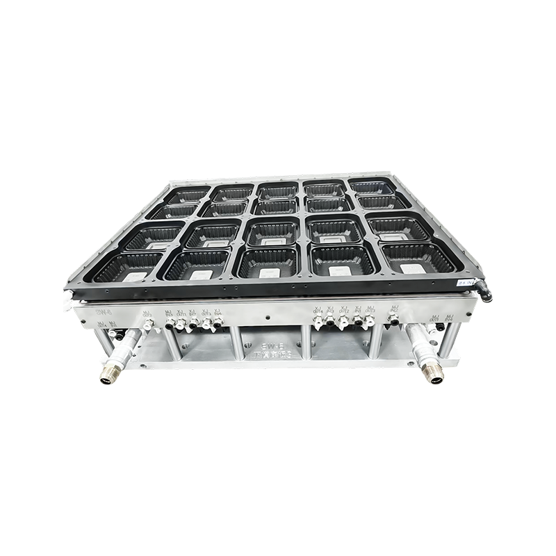
In beverage and food packaging lines, the mold is rarely the part customers notice, yet it decides almost everything about downstream cost, speed, and quality. A high-efficiency thermoforming mold is not simply a faster tool. It is a system where cavity layout, cooling channel geometry, venting, and ejection logic work together so that cycle time drops without sacrificing dimensional accuracy or seal performance.
For lids used on drink cups, soda containers, and paper bowls, the stakes are higher than they appear. A lid that seals inconsistently causes leaks during transport, customer complaints, and line stoppages. Sound mold design addresses these risks at the source, long before the first production run begins. This article breaks down the practical engineering decisions behind lid molds, using the Milk Tea Cup Lid Thermoforming Mold as a reference point for how cavity geometry and cooling balance translate into consistent output.
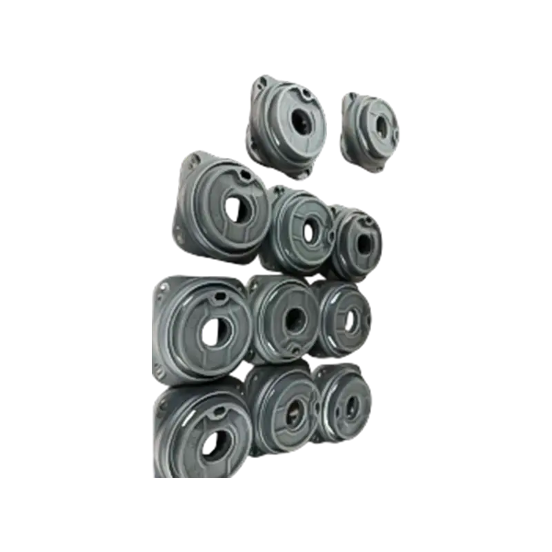
A well balanced mold typically reduces scrap rate by a measurable margin within the first production weeks, largely because thermal distribution across cavities becomes predictable rather than trial-and-error.
Mold Design Fundamentals: Materials, Cooling, and Tolerancing
Every lid mold starts with three interdependent decisions: the steel or aluminum substrate, the cooling channel pattern, and the tolerance strategy applied to sealing surfaces. Getting any one of these wrong tends to surface as a defect much later in the process, which is why experienced toolmakers treat them as a single design conversation rather than separate steps.
Material Selection and Food Contact Requirements
Lid molds that shape material destined for direct food or beverage contact must account for compatibility with food safe filament and sheet stock. This affects surface finish specifications, since a rougher cavity surface can transfer texture that traps residue or affects release consistency. Polished cavity finishes in the range typically used for food packaging reduce friction during demolding and support cleaner rim definition on the lid lip.
GD&T Tolerancing for Sealing Geometry
Dimensional control on a lid is concentrated almost entirely at the sealing lip and snap-fit ring. GD&T tolerancing is applied here with tighter bands than on cosmetic surfaces, because even small deviations in flatness or profile can compromise the seal against a cup rim. The table below summarizes how tolerance classes are typically distributed across a lid mold.
| Feature | Typical Tolerance Class | Primary Risk If Loose |
| Sealing lip profile | Tight | Leak or poor seal |
| Snap-fit ring diameter | Tight | Lid pops off or will not close |
| Vent hole placement | Moderate | Trapped air, wrinkling |
| Outer cosmetic wall | Loose | Minor visual variance only |
This distribution keeps machining cost focused where it matters, since applying the tightest band everywhere on the tool adds expense without improving functional performance.
Comparing Lid Mold Types: Milk Tea, Coke, and Paper Bowl Applications
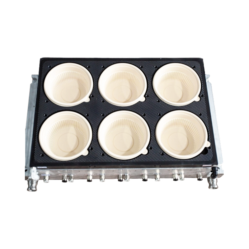
Although the three lid categories share a common thermoforming process, the mold geometry diverges based on how the container is used. A milk tea lid typically needs a cross or X-shaped cut point for straw insertion, while a soda cup lid is engineered around a stronger snap ring to withstand pressure during transport. Paper bowl lids, by contrast, prioritize a wider flange for stacking stability.

The Coke Cup Lid Thermoforming Mold illustrates this difference clearly. Because carbonated beverages generate internal pressure, the ring geometry is designed with additional wall thickness at the snap point, and the cavity depth is adjusted to prevent doming under pressure during shipping.
| Lid Type | Key Design Feature | Typical Wall Thickness Range |
| Milk tea cup lid | Straw cross-cut, domed center | Thin to moderate |
| Coke cup lid | Reinforced snap ring | Moderate to thick |
| Paper bowl lid | Wide stacking flange | Moderate, uniform |
Understanding these distinctions early prevents a common and costly mistake: adapting one mold family for a different lid category without revisiting cooling balance and ejection angle, which often results in warping or flange distortion.
How Thermoforming Molds Move From Design to Injection Molded Parts
Lid mold development typically runs through five stages, and understanding where time is actually spent helps production teams plan realistic lead times. Design and simulation usually take the longest, since cooling channel layout is iterated multiple times before cutting steel.
Once the tool passes first article inspection, the same cavity produces both the thermoformed lid shell and, in many production lines, complementary injection molded parts such as reinforcing rings or straw stoppers that are assembled downstream. Keeping both processes aligned on the same dimensional baseline avoids fit issues at final assembly.
Why Mass Customization Depends on Modular Mold Architecture
Brand owners increasingly request seasonal lid variations, region-specific labeling cutouts, or minor geometry tweaks without a full retool. This is only economical when the mold base is built with modular inserts rather than a single monolithic cavity block.

The Paper Bowl Lid Thermoforming Mold is a good example of this approach: the flange and locking ring are held on replaceable inserts, so a design change to the flange profile does not require remaking the entire tool base. This supports mass customization without the cost penalty typically associated with frequent tooling changes.
Where Modularity Pays Off
- Seasonal or promotional lid pattern changes
- Regional straw-hole size variations
- Incremental wall thickness adjustments for material cost testing
- Faster recovery when a single cavity insert wears or is damaged
Production efficiency gains from modularity are cumulative rather than immediate. The first insert swap may take similar time to a full retool, but each subsequent change becomes faster as the team standardizes fixture alignment and insert cataloging.
Common Defects and Practical Troubleshooting Approaches
Most lid mold defects trace back to one of three root causes: uneven cooling, incorrect sheet temperature at forming, or vent placement that cannot evacuate trapped air fast enough. The table below groups the most frequently reported issues with their typical corrective direction.
| Defect | Likely Cause | Corrective Direction |
| Thin spot at lip | Uneven material draw | Adjust plug assist timing |
| Webbing between cavities | Excess sheet sag | Reduce preheat time |
| Cloudy or hazy surface | Mold temperature mismatch | Rebalance cooling zones |
| Warped flange after cooling | Asymmetric cooling rate | Redesign channel spacing |
| Trapped air marks | Insufficient venting | Add or reposition vent holes |
Tracking defects against cavity position, not just defect type, often reveals a pattern tied to a specific cooling zone rather than a process-wide problem. This narrows troubleshooting significantly and avoids unnecessary full-tool rework.
Maintenance Practices That Extend Mold Lifecycle
A lid mold in continuous production accumulates wear unevenly, with the sealing lip and vent edges typically showing the earliest signs of degradation. A structured maintenance rhythm keeps output consistent across the tool's working life.
- Inspect sealing lip geometry against baseline measurements at fixed run intervals
- Clean vent holes to prevent gradual air-evacuation slowdown
- Check cooling line flow rate for early signs of scale buildup
- Verify ejector pin alignment to catch early wear before it marks parts
- Log defect rate by cavity to flag localized wear before it spreads
Molds maintained on this kind of schedule generally sustain tighter dimensional consistency over a longer run count than those inspected only after a defect is already visible on finished parts.
Frequently Asked Questions
Q1: What is the typical cavity count for a lid thermoforming mold?
Cavity count depends on cup diameter and machine platen size, but mid-volume production lines commonly run multi-cavity layouts to balance cycle time against tooling cost. Higher cavity counts reduce per-unit cost but raise the complexity of cooling balance.
Q2: How does GD&T tolerancing affect lid sealing performance?
Tight tolerancing on the sealing lip and snap-fit ring ensures consistent contact against the container rim across every cavity. Loose tolerancing in these zones is a common cause of intermittent leak complaints even when the overall part looks visually correct.
Q3: Can one mold base support both milk tea and paper bowl lid styles?
Only with a modular insert design. A fixed monolithic cavity typically cannot accommodate the geometry differences between a straw-cut lid and a wide-flange bowl lid without a full cavity rebuild.
Q4: What causes inconsistent lid thickness across cavities?
This is most often linked to uneven sheet preheat or asymmetric cooling channel spacing, which causes some cavities to draw material differently than others during the same cycle.
Q5: How does mold design influence overall production efficiency?
Cooling balance and vent placement directly affect cycle time, since a mold that cools unevenly forces the operator to slow the cycle to protect the slowest-cooling cavity. Addressing this in the design phase avoids sacrificing speed later.