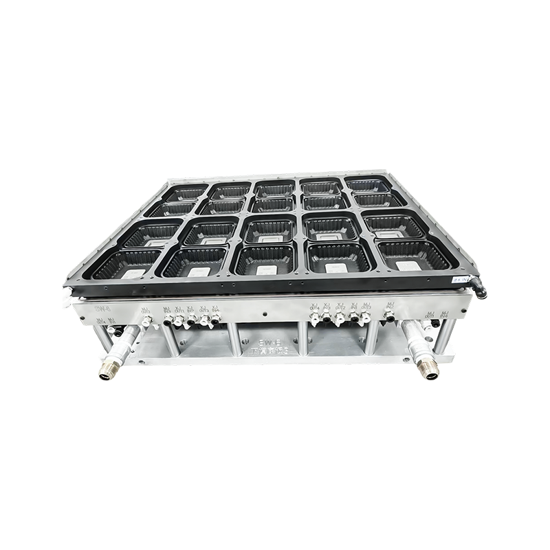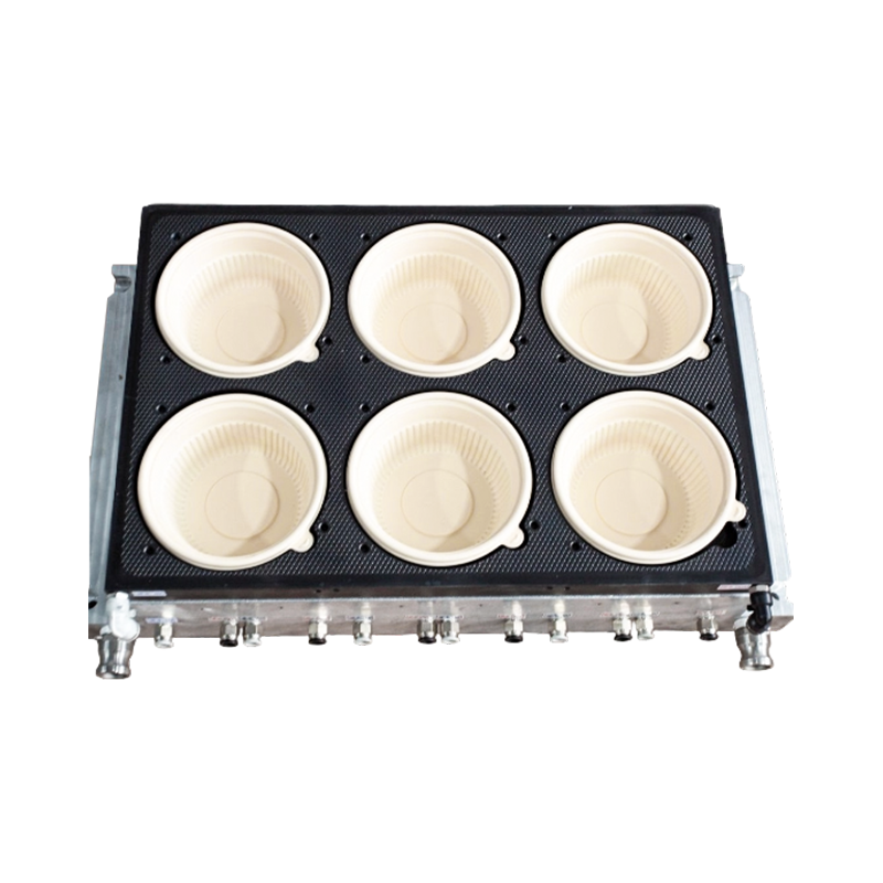


 en
en  English
 Español
 عربى
عربى
What Sets Thermoforming Mold Design Apart From Injection Tooling
Thermoforming and injection molding solve the same basic problem, turning raw plastic into a usable shape, but the tooling logic behind each process is fundamentally different. Injection molds are built to withstand high injection pressure and hold a closed cavity while molten resin fills it under force. Thermoforming molds work against a much gentler load: a heated sheet is draped or vacuum-pulled over a single-sided tool, so the design challenge shifts away from pressure containment and toward heat management, air evacuation, and surface replication.
That difference shows up in almost every part of the engineering process. Injection tooling needs heavy steel blocks, precision-matched core and cavity halves, and hot runner systems capable of holding thousands of pounds of clamp force. Thermoforming tooling, by contrast, is often machined from aluminum or a composite tooling board, since the forces involved are limited to atmospheric vacuum pressure and light mechanical assist rather than high-pressure injection. This lighter structural requirement is precisely what allows thermoforming molds to be produced faster and at a fraction of the cost of a comparable injection tool.
For packaging applications, that cost and speed advantage matters because product changeovers happen often. A snack tray program might need three or four cavity variants across a single season, and a converter simply cannot justify a new injection tool for each one. A well-engineered thermoforming mold still has to deliver consistent wall thickness, clean demolding, and dimensional stability across tens of thousands of cycles, and that consistency starts on the design table, not the shop floor.
It is also worth noting where the two processes overlap rather than compete. Some packaging programs use injection-molded lids paired with thermoformed bases, precisely because each process is suited to a different part of the geometry: the lid benefits from injection molding's tight tolerance on snap features, while the base benefits from thermoforming's low tooling cost for a large, shallow shape.
Working definition: mold design in this context refers to the complete engineering package, cavity geometry, venting layout, cooling circuit, and surface finish, that determines how a heated sheet forms into a finished packaging part.
How Core Design Decisions Shape Packaging Performance
Every packaging mold, regardless of end shape, is built around the same handful of variables. Getting these right early avoids costly rework once a tool is already cut.
Insufficient draft causes sheet webbing to grip the mold wall during ejection, leading to whitening or tearing at corners.
Deep-draw areas thin out fastest; rib placement and pre-stretch assist geometry redistribute material before it locks against the tool.
Vent hole size and spacing control how quickly trapped air escapes, which directly affects surface texture and cycle time.
Channel routing near thick sections shortens dwell time and reduces post-mold warpage in stacked packaging.
Cavity count is another decision with performance consequences well beyond output volume. The table below compares single-cavity and multi-cavity tooling across the factors that matter most for packaging programs.
| Factor | Single-Cavity Mold | Multi-Cavity Mold |
|---|---|---|
| Tooling lead time | Shorter | Longer |
| Per-part cost at volume | Higher | Lower |
| Dimensional consistency | Easier to control | Requires tighter process balance |
| Best fit | Prototyping, short runs | High-volume packaging lines |
Multi-cavity tooling introduces a variable that single-cavity designs never face: cavity-to-cavity balance. Every cavity in a shared plate has to receive the same sheet temperature, the same vacuum draw, and the same cooling exposure at the same moment, or the parts coming off one side of the tool will differ measurably from the other. Designers address this by mapping heater zone layout against cavity position before the plate is ever cut, rather than trying to correct imbalance later through trial and error on the production floor.
Material selection for the mold itself is a related decision that gets less attention than it deserves. Aluminum tooling machines quickly and conducts heat efficiently, which suits short-to-medium production runs. Harder tooling alloys or plated surfaces cost more up front but hold tighter tolerance over a longer service life, which matters more once a packaging program is expected to run for several years without a full retool.
Engineering a lunch box thermoforming mold for Multi-Compartment Packaging
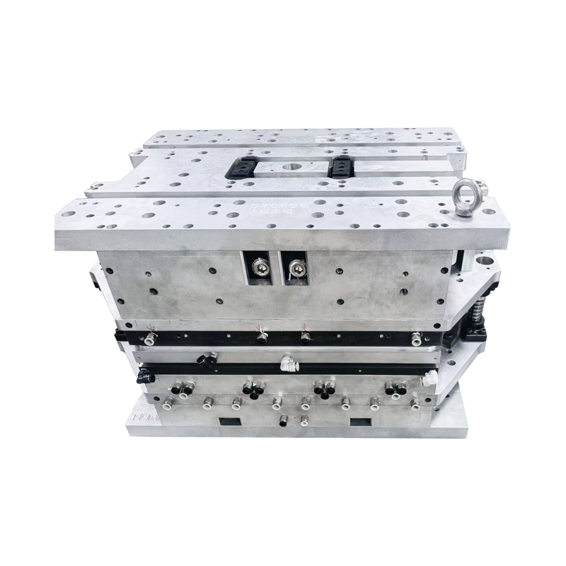
Compartmented food packaging places unusual demands on tooling because each internal divider is effectively its own small draw, nested inside the outer cavity. A poorly balanced divider layout starves material from adjacent walls, leaving one compartment thick and the next dangerously thin near the base.
Practical engineering priorities for this category include:
- Rounded internal corners on every compartment wall to prevent stress concentration during stacking and transport
- Matched draft angles across divider walls so ejection force is distributed evenly
- Vent placement at the deepest point of each compartment, not just the outer perimeter
- Food-contact-appropriate surface finish specified before machining, since polishing after heat treatment adds cost
Because compartment counts and proportions vary by menu format, mold designers usually build a family of interchangeable insert plates rather than a single fixed cavity, which lets a converter adjust compartment ratios without commissioning an entirely new tool.
Lid and base fit is another detail specific to this category. Multi-compartment trays are frequently paired with a flat or domed lid that seals around the full perimeter, so the base mold has to hold its flange dimension within a tight band even as internal dividers pull material unevenly during the forming stroke. Designers typically add localized pre-stretch geometry near the tray's outer edge specifically to protect that flange dimension, since a flange that shrinks out of tolerance will not seal reliably even if every compartment inside looks correct.
Stack height control matters just as much for logistics as it does for the mold itself. Distribution centers price shipping largely by volume, so a compartment tray designed with slightly steeper interior walls and a shallower overall draw can nest more tightly during transport without changing the usable capacity the end customer sees on the shelf.
Cup Thermoforming Mold Design for High-Speed Production Lines
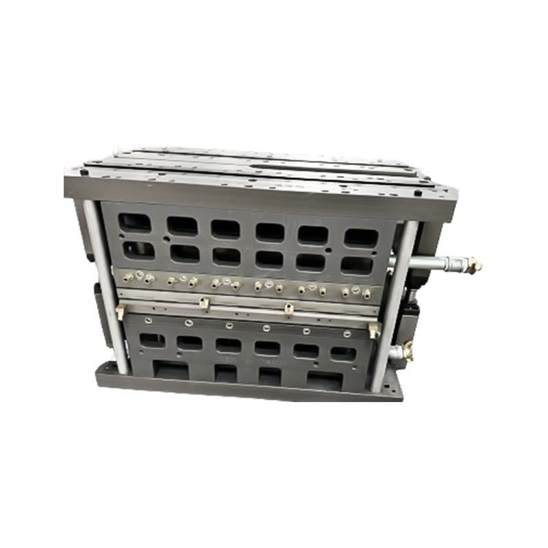
A cup thermoforming mold operates under production speeds that most other packaging tooling never sees. Beverage and dairy cup lines commonly run continuous roll-fed sheet through form, cut, and stack stations in a matter of seconds per cycle, so the mold has to release cleanly every single time without manual intervention.
Three geometry details carry outsized weight in this category:
| Feature | Function | Design Risk If Ignored |
|---|---|---|
| Rim radius | Seal integrity with lidding film | Leakage or poor lid adhesion |
| Stacking lug | Consistent nesting depth | Jamming in automatic dispensers |
| Sidewall taper | Clean release from core | Whitening, cracking, or drag marks |
Cycle time is often the deciding factor in cup mold profitability. In typical high-speed cup tooling, cooling accounts for close to half of the total cycle, so cooling channel proximity to the sidewall and base has a direct, measurable effect on how many cups a line produces per hour.
Base geometry deserves separate attention from sidewall design because the two zones cool at different rates. A cup base is thicker relative to its surface area than the tapered sidewall above it, so if cooling channels are spaced evenly along the whole cavity without accounting for that difference, the base becomes the bottleneck that sets the pace for the entire line, even though the sidewalls finish cooling much sooner.
Trim and stack tooling downstream of the forming station also feeds back into mold design decisions upstream. If the cup rim is not held to a tight roundness tolerance at the forming stage, automatic stacking equipment further down the line will jam intermittently, and diagnosing that kind of fault is far more expensive once a line is already running than catching it during the initial cavity design review.
Why Hinge and Seal Geometry Define rectangular clamshell packaging box thermoforming mold Quality
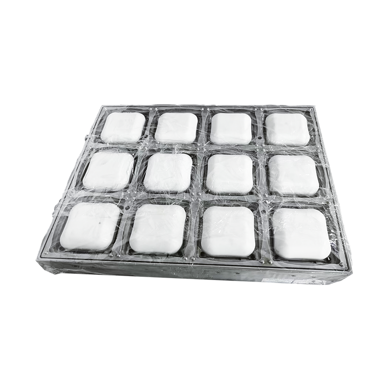
Clamshell packaging lives or dies on two features: the hinge and the sealing flange. Both are thin-wall zones by design, and both are exactly where sheet thinning is hardest to control, which makes this mold category one of the more demanding in the packaging sector.
The hinge line needs enough controlled thinning to fold repeatedly without whitening or snapping, but not so much that the package loses structural rigidity at the fold. Mold designers typically manage this with a shallow scoring rib rather than relying on natural sheet stretch alone, since natural stretch varies with sheet temperature and is harder to hold within tolerance across a production shift.
The sealing flange, meanwhile, has to stay dimensionally flat around the full perimeter so that heat sealing or ultrasonic welding forms a continuous bond. Flange flatness is checked against a tolerance band during mold trial, and even small deviations, often under half a millimeter, can create a channel where a seal should be continuous.
Design tip: building a slight positive draft into the flange support ribs makes trimming more consistent, since it keeps the sheet from lifting away from the trim edge before the cutting die engages.
Locking geometry is the third feature worth planning early, even though it sits away from the hinge and the seal. Tab-and-slot closures on the lid side of a clamshell need enough engagement to hold securely on a store shelf, but not so much that a customer struggles to open the package at home. Because this feature is usually tested by hand during design review rather than measured purely on paper, most experienced toolmakers build one working sample cavity insert before committing to a full multi-cavity plate, specifically so the closure force can be checked physically rather than estimated from simulation alone.
How CAD Software Systems Support Mold Engineering Standards
Modern mold engineering rarely starts with a blank sketch. Most programs move through a structured digital workflow before a single block of tool steel or aluminum is machined, and skipping steps in that sequence is one of the most common sources of costly redesign.
- Product model import and wall thickness analysis
- Draft angle and undercut check against the parting direction
- Cavity layout and shrinkage compensation
- Forming simulation to predict thin spots before cutting metal
- CNC toolpath generation and machining
- Trial run, measurement, and design correction
The diagram below shows how this sequence typically flows from concept through to production release.
Standardizing this workflow also gives packaging manufacturers a common reference point when comparing mold engineering proposals from different toolmakers, since simulation output and shrinkage allowances can be reviewed against the same benchmarks rather than taken on faith.
Forming simulation deserves particular emphasis because it is the step most often shortened under schedule pressure. A simulation pass predicts where sheet material will thin out before any metal is cut, essentially giving the design team a preview of the trial run result days or weeks earlier than a physical test could provide it. Skipping or rushing this step tends to shift the discovery of a thin-wall problem from the design phase, where a correction costs almost nothing, to the trial run phase, where it can mean re-machining an already-finished cavity.
Documentation standards matter just as much as the software itself. A mold engineering package that records draft angles, vent hole coordinates, and shrinkage factors in a shared, structured file lets a second toolmaker pick up maintenance or a repeat order years later without reverse-engineering the original design intent from the physical tool alone.
Vacuum Forming Process Parameters That Influence Mold Life
Vacuum forming is the mechanism that actually pulls the heated sheet against the cavity, and the parameters governing that step affect not just part quality but how long the mold itself stays in tight tolerance.
| Parameter | Typical Range | Effect on Mold Life |
|---|---|---|
| Sheet surface temperature | Material-dependent, controlled per resin | Overheating accelerates thermal fatigue in cavity surface |
| Vacuum draw time | Short, matched to part depth | Excess draw time slows cycle without improving detail |
| Cooling dwell | Often the largest share of cycle time | Undercooling causes part distortion and mold contamination from soft plastic |
| Mold surface temperature | Kept below sheet softening point | Poor thermal control causes uneven shrinkage across the cavity |
These parameters do not act independently of one another, which is part of why process setup for a new mold typically takes longer than expected. Raising sheet temperature to improve detail replication, for example, usually also extends the cooling dwell needed afterward, which offsets the cycle-time gain a converter was hoping for. Experienced process engineers treat the parameter set as a system to be balanced together rather than a checklist to be optimized one line at a time.
Mold surface condition compounds these effects over time. A cavity surface that starts out polished to a fine finish will gradually pick up microscopic wear from repeated contact with hot plastic sheet, and once that wear reaches a certain point, parts coming off the tool start showing inconsistent gloss or faint drag lines even though every process parameter on the line has stayed the same. Scheduling periodic surface inspection, rather than waiting for a visible defect to appear on the production floor, is one of the more cost-effective habits a converter can build into a maintenance plan.
Common Design Pitfalls in Thermoform Tooling and How to Avoid Them
- Ignoring shrinkage direction: plastics shrink differently along and across the sheet draw direction, so a single flat shrinkage factor across a cavity often produces out-of-round rims that only become obvious once the mold is already cut and a full trial run has been completed.
- Undersized vent holes: vents that are too small slow air evacuation and leave faint surface marks that show up under retail lighting, and simply drilling a few extra vents after the fact rarely fixes the pattern without also revisiting hole placement relative to the deepest draw points.
- Skipping forming simulation: thin-spot prediction software catches problems on screen that would otherwise surface only after a physical trial run, at far higher cost in both machining time and material scrapped during setup.
- Uniform draft across varied depths: deep-draw zones typically need more draft than shallow ones, and applying one blanket angle across the whole cavity often causes localized sticking at exactly the point where a part is already thinnest and most fragile.
- Late cooling channel placement: routing cooling lines after the cavity geometry is finalized, rather than alongside it, frequently leaves thick sections without adequate heat removal, which shows up later as a stubborn cycle-time ceiling that no amount of process tuning can fully resolve.
- Underestimating trim tool alignment: a forming cavity and its downstream trim die are often designed by different teams, and small misalignment between the two shows up as flash or an uneven cut edge even when the forming cavity itself is dimensionally perfect.
Frequently Asked Questions on Thermoforming Mold Design
Q1: How long does it typically take to design and build a packaging thermoforming mold?
Timelines vary with cavity count and complexity, but most single or low-cavity packaging molds move from finalized design to first trial run within a few weeks, while multi-cavity production tooling with tighter tolerance requirements and more extensive simulation review can take considerably longer to complete.
Q2: What is the difference between a prototype mold and a production mold?
A prototype mold is usually built from a softer, faster-to-machine material to validate geometry and fit before committing to a hardened, longer-life production tool designed for continuous high-volume runs, since cutting a full hardened tool before geometry is confirmed adds unnecessary cost and risk.
Q3: How does mold design affect the recyclability of packaging?
Consistent wall thickness and clean trim lines reduce material waste per part, and uniform gauge across the cavity makes downstream sorting and recycling streams more predictable, since automated sorting equipment often relies on consistent material thickness to classify packaging accurately.
Q4: Can one mold produce different compartment layouts for lunch box packaging?
Some tooling is built with interchangeable insert plates that allow compartment ratios to change without replacing the entire mold base, though this flexibility needs to be planned during the original design phase rather than added after the base mold is already finished.
Q5: What causes uneven wall thickness in a finished thermoformed part?
Uneven thickness usually traces back to draft angle imbalance, uncontrolled sheet pre-stretch, or cavity geometry that lets material lock against the mold wall before deeper sections are fully formed, which is why forming simulation during the design stage is so valuable for catching the issue early.
Q6: Does mold design influence how well a package seals?
Yes, flange flatness and rim geometry are set entirely by the mold, so any seal or lid-fit problem traced back to a production line almost always has its root cause in the original cavity design rather than in the sealing equipment itself.