

 en
en  English
 Español
 عربى
عربى
Why Rapid Prototyping Sits Between an Idea and a Mold
A thermoforming mold is expensive to cut, difficult to modify once machined, and slow to replace if a wall section is too thin or a draft angle is wrong. That is exactly why experienced toolmakers do not move straight from a sketch to CNC-machined aluminum. Instead, they insert a rapid prototyping stage that catches geometry problems while they are still cheap to fix.
This article walks through the practical sequence that connects a CAD file to a finished mold: building the model with printability in mind, producing a proof of concept, testing functional prints under real conditions, and, where an existing part needs to be replicated, reverse engineering it into usable data. Along the way we look at how two common tooling types, a cup lid thermoforming mold and a round lidded packaging box thermoforming mold, typically move through this process.
CAD Design for 3D Printing: Building the Model Right the First Time
A CAD model built for a thermoforming mold has to satisfy two different rule sets at once. It must respect thermoforming logic, such as draft angles, uniform wall reduction, and coring for undercuts, and it must also be printable, meaning the geometry can be built layer by layer without warping, drooping, or trapping support material inside a cavity.
Design Habits That Prevent Rework Later
- Model the part at its intended shrink-corrected size rather than adjusting after the first print fails.
- Keep wall thicknesses consistent; sudden jumps create sink marks in a print and uneven cooling in a real mold.
- Add draft angles at the CAD stage, not as an afterthought during machining.
- Separate complex undercuts into inserts that can be printed and tested independently.
- Export in a format that preserves surface tolerance, since a coarse mesh export can hide small radius errors.
Where 3D Printing Tolerances Actually Matter
Desktop and industrial 3D printers vary widely in achievable tolerance, typically somewhere between two tenths and half a millimeter depending on the process and machine condition. That tolerance band is usually fine for checking fit, stacking, and lid engagement, but it is not tight enough to substitute for the final machined mold surface. The purpose of the printed part is to validate geometry logic, not to serve as the production tool itself.
Proof of Concept: Choosing the Right Prototyping Route
Once the CAD model is ready, the next decision is how to prove the concept before committing to steel or aluminum. Additive manufacturing is the default choice for early proof of concept because it removes the lead time and cost of machining a test block, but it is not the only option and is not always the right one for every stage.
| Method | Typical Lead Time | Best Use | Main Limitation |
|---|---|---|---|
| Desktop 3D Printing | Hours | Form and fit checks, early design review | Lower surface accuracy, limited heat resistance |
| Industrial Additive Manufacturing | 1 to 3 days | Functional testing, stacking and nesting checks | Higher cost per part than desktop printing |
| CNC Machined Prototype | 3 to 7 days | Surface finish and dimensional confirmation | Slower and costlier than printing |
| Soft Tooling Sample | 1 to 2 weeks | Small-batch trial runs before hard tooling | Not suited for high-volume validation |
Most projects blend these routes rather than picking just one. A desktop print might confirm that a lid clicks onto a rim correctly, while a small CNC sample later confirms how the same geometry behaves once it is cut from the mold material itself.
Functional 3D Prints: Testing Fit, Draft, and Wall Behavior
A functional prototype goes beyond looking correct on a screen. It has to survive the same handling the finished packaging will face: stacking, nesting, sealing, and repeated opening and closing. Testing at this stage typically checks the following points before any cutting begins on the actual mold block.
Checklist Before Approving a Design for Tooling
- Confirm the lid or lidded box seats fully without excessive force or looseness.
- Check draft angles by removing the printed part from a simple test fixture, simulating mold release.
- Stack five to ten printed units to confirm consistent nesting height.
- Verify rim thickness stays within the tolerance range agreed with the material supplier.
- Run the part through a basic drop or compression test if the packaging will carry weight.
Failures found here are inexpensive to correct; the same failures found after mold machining usually mean added weld repair, re-cutting a cavity, or in the worst case, scrapping a mold block entirely.
Reverse Engineering: When You Start From a Physical Part Instead of a Blank Page
Not every project begins with a clean CAD file. Sometimes a customer supplies a sample lid or box and asks for a matching mold. In that case, reverse engineering bridges the gap between a physical object and usable tooling data.
A Practical Reverse Engineering Sequence
| Step | Activity | Output |
|---|---|---|
| 1 | 3D scan or manual measurement of the sample part | Point cloud or measured dimensions |
| 2 | Surface reconstruction into a clean CAD model | Editable solid model |
| 3 | Comparison of reconstructed model against the original scan | Deviation report |
| 4 | Correction of draft, wall thickness, and shrink allowance | Manufacturing-ready CAD file |
| 5 | 3D printed check part against the physical sample | Confirmed match before mold cutting |
The deviation report in step three matters more than it might seem. A part that looks identical by eye can still be off by a fraction of a millimeter in wall thickness, which is enough to change how it behaves once heated plastic is drawn over the mold surface.
How to Make a Mold: From Approved Prototype to Cut Tooling
Once a design passes prototype testing, whether it started from a fresh CAD design or from reverse engineering, the project moves into the actual mold-making stage. The diagram below summarizes the general path most thermoforming molds follow after prototype approval.
Vacuum hole placement and cooling channel layout are two areas where the printed prototype has real influence. Testing where webbing or thin spots occur on a functional print helps a toolmaker decide where extra vacuum draw is needed once the mold is cut.
Applying the Workflow: Two Common Mold Types
The general sequence above applies to almost any thermoforming mold, but the details shift depending on part geometry. Two frequently produced examples illustrate the differences well.
Cup Lid Thermoforming Mold

A cup lid thermoforming mold depends heavily on rim engagement accuracy. Prototype testing usually focuses on how consistently the lid snaps onto varying cup rim tolerances, since even small rim variation across a production run can cause a lid that fits perfectly on one cup and loosely on another.
Round Lidded Packaging Box Thermoforming Mold
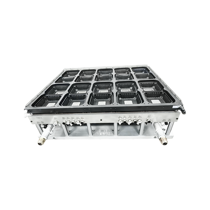
A round lidded packaging box thermoforming mold introduces a different challenge: base stability. Prototype testing typically checks whether the base resists flexing under stacked weight and whether the lid seam stays consistent all the way around the circumference, not just at one measured point.
Common Pitfalls When Moving From Prototype to Mold
Skipping shrink compensation is the single most common source of mismatched parts. A print made at nominal CAD size will not match a molded part unless the CAD file already accounts for material shrink.
- Approving a design based on a single printed sample rather than a small batch, which hides part-to-part variation.
- Ignoring draft angle warnings from slicing or CAD software because a print still releases from a simple test fixture.
- Treating reverse-engineered data as final without a deviation check against the original sample.
- Changing wall thickness late in the process without re-testing vacuum draw behavior.
Frequently Asked Questions
Q1: How accurate does a 3D printed prototype need to be before approving a mold design?
It needs to be accurate enough to confirm fit, draft angles, and general wall behavior, typically within the tolerance range of the printing process itself. It does not need to match final production tolerance, since that level of accuracy comes from the machined mold, not the prototype.
Q2: Can a functional 3D print replace a small production trial run?
Not fully. A functional print is useful for checking geometry and mechanical fit, but it cannot replicate the exact surface finish, heat transfer, or vacuum behavior of a machined mold, so a trial run is still recommended before full production.
Q3: What is the difference between a proof of concept and a functional prototype?
A proof of concept confirms that the basic idea works, such as whether a lid shape is feasible at all. A functional prototype goes further, testing the part under conditions closer to real use, including stacking, sealing, and repeated handling.
Q4: When is reverse engineering necessary instead of starting a new CAD design?
Reverse engineering is used when a physical sample already exists and needs to be matched closely, such as replacing an obsolete mold or matching a competitor packaging format for compatibility purposes.
Q5: How many prototype iterations are typical before a mold is cut?
This varies by part complexity, but most straightforward lid or box geometries go through two to three iterations, while more complex undercut geometry may require additional rounds of testing.