 English
 Español
 عربى
عربى
Understanding the Mechanics of Prototyping in Thermoforming Processes
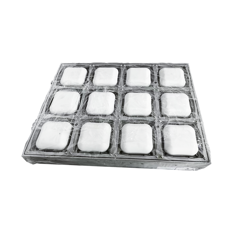
Industrial thermoforming operations demand extreme precision during early-stage development cycles. In high-volume packaging applications, transition phases from conceptual 3D renders to physical reality require strict validation of material behavior, cooling shrinkage, and geometric fidelity. Utilizing traditional hard tooling strategies for verification causes lengthy schedules and high capital risks. Integrating a robust strategy centered around cup thermoforming mold development allows manufacturing engineers to test physical polymers before final production steel cutting occurs. This intermediate testing sequence provides empirical data regarding sheet stretch behavior, molecular orientation, and cooling performance metrics under realistic production shop-floor conditions.
By defining what is rapid prototyping within heavy industrial parameters, tooling engineers isolate specific performance metrics such as plug-assist penetration depth, vacuum distribution rates, and sidewall thinning profiles. The core objective of rapid prototyping is to compress product iteration intervals from months down to mere hours, allowing structural evaluations to occur under active pressure conditions. Industrial applications necessitate a deep look into how these plastic sheets deform over a temporary mold topology, ensuring that flaws are corrected before millions of cycles are run on commercial machinery.
When executing an industrial packaging roadmap, the speed at which a design can be validated influences the time-to-market advantage. Engineers use temporary molds to analyze material flow across complex geometries. For instance, high-impact polystyrene stretches differently compared to polyethylene terephthalate under the same vacuum load. Through temporary tool testing, engineers can observe these nuances first-hand, allowing them to modify corner radii, change draft angles, or alter depth-to-draw ratios without incurring the major rework costs associated with production-grade tooling blocks.
Furthermore, prototyping serves as a key bridge between conceptual design teams and practical manufacturing operators. A design that appears structurally sound in a virtual simulation environment might encounter severe material failure when subjected to high-speed vacuum forces. Prototyping highlights these practical limitations early, revealing processing issues such as web lines, structural warping, or severe stress whitening along critical corners. Identifying these mechanical bottlenecks before building the final multi-cavity production line saves significant time, resource allocations, and engineering hours.
Core Methodologies of Thermoforming Rapid Tooling
Modern thermoform toolrooms separate prototyping systems into distinct categories based on production run requirements, thermal capacity, and structural density. Standard thermoforming rapid tooling relies on additive manufacturing, subtractive machining of polyurethane slabs, or filled epoxy resins castings over secondary models. Each technology presents trade-offs regarding surface finish, durability under mechanical vacuum stress, and thermal degradation limits. Selecting the optimal methodology depends heavily on the target production volume, structural complexity of the part, and the physical properties of the chosen thermoplastic material.
Additive Tooling vs Subtractive Machining for Prototype Tooling
Selecting the correct approach dictates the fidelity of the prototype thin-wall parts produced. When creating highly detailed components like a cup lid thermoforming mold, subtle geometric undercut configurations and retention snaps must lock precisely onto mating containers. This requires an in-depth understanding of material behaviors across different forming techniques. Additive processes like stereolithography provide exceptional resolution for fine details, whereas subtractive machining of composite timbers delivers superior structural strength and thermal stability for larger format industrial projects.
| Prototyping Technology | Common Tooling Materials | Dimensional Accuracy | Thermal Limit | Optimal Application Scope |
|---|---|---|---|---|
| Stereolithography (SLA) | High-Temp Ceramic Resins | ±0.05 mm | 120 °C | Intricate Lid Snaps and Closures |
| Fused Granular Fabrication | Carbon Fiber Filled PEI | ±0.15 mm | 180 °C | Large Structural Industrial Trays |
| CNC Subtractive Machining | High-Density Polyurethane Foam | ±0.10 mm | 85 °C | Deep-Draw Shallow Trays and Blispacks |
| Vacuum Resin Casting | Aluminum-Filled Epoxies | ±0.08 mm | 150 °C | Multi-Cavity Pre-Production Runs |
Machining dense polyurethane model boards remains a popular technique due to its fast processing speeds and excellent surface quality. These materials are easy to machine using high-velocity CNC spindles, letting toolrooms produce a complete mold cavity within a few hours. However, because polyurethane features low thermal conductivity, these tools trap heat quickly during repetitive operations. This makes them ideal for short validation runs of 10 to 20 samples, but less suitable for longer pre-production trials where maintaining tool temperature consistency is critical for monitoring part shrinkage.
Conversely, aluminum-filled epoxy casting resins offer enhanced thermal performance by incorporating metallic powders within a liquid polymer base. This composition increases the tool thermal conductivity, allowing it to withstand longer sample cycles without experiencing significant dimensional drift. Crafting a cast epoxy tool involves pouring the liquid mixture over a machined pattern or a 3D printed master model. This approach represents a highly effective method for replicating fine surface patterns, such as leather textures, micro-engravings, or debossed safety logos, directly onto the prototyped thermoformed parts.
The Digital to Physical Transition Architecture
Executing functional engineering trials requires systematic execution of prototype mold fabrication pipelines. Any deviation in draft angle integration or vacuum vent distribution will ruin early assessment data. This visual workflow map outlines the exact chronological phases involved in transforming raw packaging concepts into verified thermoformed units.
During the design phase, critical structural adjustments must be integrated before launching physical tools. Thermoform mold design engineers carefully specify structural requirements to ensure parts release cleanly from the cavities without distortion:
- Draft Angles: A minimum value of 2 to 3 degrees for female cavities, and 4 to 5 degrees for male plugs, must be applied to prevent part dragging and surface scuffing during ejection cycles.
- Vacuum Vent Positioning: Vent holes must be strategically placed in deep corners, sharp transitions, and interior structural ribs to ensure complete sheet adaptation under atmospheric pressures.
- Radii Configuration: Every corner transition must maintain a minimum radius equal to or greater than the starting sheet thickness to prevent catastrophic stress concentration zones.
The layout and size of the vacuum holes represent another critical variable during the prototyping phase. If vent holes are drilled too large, the hot polymer sheet will migrate into the openings, leaving cosmetic defects or small pimples on the surface of the finished packaging. Conversely, if the vents are too small or spaced too far apart, pocketed air can become trapped between the tool surface and the plastic sheet. This leads to soft, rounded edges and prevents the part from achieving its target crisp, sharp geometry. Prototyping lets engineers refine vacuum placement configurations, identifying the ideal balance required to pull a perfect part without causing physical markings on the plastic surface.
Additionally, engineers analyze the mechanical effects of the clamping framework during these initial development loops. The clamping ring must hold the plastic sheet securely around its entire perimeter to prevent slipping as the material transitions from flat sheet to three-dimensional cavity. Slipping during the forming stage alters the material distribution profile, causing uneven thinning and unpredictable weak points. Prototyping verifies that the draw-down mechanics and nesting forces function perfectly together before operators assemble the complete production tool layout.
Specialized Applications in Rigid Consumer Packaging
The consumer goods landscape relies on ultra-fast iteration loops to meet seasonal retail shelf demands. Deploying tailored rapid prototyping for packaging protocols allows cross-functional teams to validate seal integrity, vertical stack capacities, and multi-unit nests prior to commercial sign-offs. For example, testing a newly engineered high-clarity polypropylene profile requires complex thermal control due to the polymer narrow forming window. This phase ensures the material maintains structural and visual properties through every step of production.
Structural Rigidity Protocols for Meal Containers
When developing complex geometries such as a lunch box thermoforming mold, the prototype tool must reproduce critical features like multi-compartment divider walls, anti-fog ventilation channels, and perimeter snap rims. If the prototype material exhibits poor thermal dissipation, the plastic sheet remains soft too long, leading to localized wall thinning at the lowest corners. Engineers utilize high-density resin boards or metal-powder loaded composites to match the thermal absorption properties of permanent industrial production setups.
Rigid food trays must perform under diverse ambient conditions, such as freezing storage temperatures and high-heat microwave environments. Prototyping lets engineers subject real thermoformed sheet samples to environmental stress testing before manufacturing the permanent multi-cavity production tool. These physical evaluations confirm that the structural ribs along the container sides provide sufficient top-load crush strength, preventing the packaging from buckling when stacked on retail pallets or automated distribution shelves.
Furthermore, prototyping reveals how the individual compartments interact with sealing lidding films. In multi-compartment food prep containers, any slight distortion or bowing across the center divider walls will prevent the top film from bonding properly. This leads to cross-contamination between food sections and shortens product shelf life. Running short test batches on a prototype tool allows engineers to evaluate seal flat tolerances across all internal partitions, ensuring consistent quality before committing to full-scale commercial manufacturing systems.
Analyzing Tool Wear and Structural Deformation under Vacuum Loads
During a typical vacuum forming cycle, the prototype tooling body must withstand substantial structural stresses. When a heated thermoplastic sheet drops over the tool, it creates a sealed chamber that rapidly evacuates air, generating a strong uniform pressure field across the exposed surfaces. At the same time, mechanical plug assists press downward with significant forces, focusing localized shear stresses on thin-walled columns or narrow projecting cores.
If the prototype mold material lacks sufficient compressive yield strength, these repetitive mechanical loads will cause subtle deformations over time. For instance, sharp corner configurations can gradually round off, or tall vertical cores may shift off-center. These dimensional deviations compromise the accuracy of validation testing. Therefore, engineers must select tooling materials that maintain structural stability under both elevated forming temperatures and high mechanical vacuum loads.
The table below details the performance characteristics and lifespans of common temporary tooling materials under typical industrial conditions, helping engineers select the most appropriate option based on testing requirements:
| Tool Core Material | Compressive Strength | Flexural Modulus | Expected Tool Life | Surface Quality Rating |
|---|---|---|---|---|
| Medium Density MDF Board | 25 MPa | 3200 MPa | 5 to 10 Cycles | Low (Porous Fiber Grain) |
| Polyurethane Tooling Board | 65 MPa | 4100 MPa | 20 to 50 Cycles | Medium (Fine Matte Finish) |
| Aluminum Filled Epoxy Resin | 110 MPa | 7800 MPa | 100 to 300 Cycles | High (Smooth Semi-Gloss) |
| 3D Printed Ceramic Composite | 145 MPa | 9500 MPa | 50 to 150 Cycles | Very High (Crisp Resolution) |
This comparative overview shows that while wood fiber boards provide a fast, cost-effective option for basic geometric checks, they degrade too quickly to provide accurate structural data across multiple test cycles. For comprehensive testing programs that require evaluating dozens of parts for consistency, high-density synthetics or filled resins represent a more reliable selection. These advanced materials preserve sharp corner definitions, flat surfaces, and critical interlock dimensions through many forming cycles, ensuring the collected validation data remains accurate and repeatable.
Material Selection Criteria for Prototype Tooling Bodies
Selecting the optimal medium for temporary mold cores involves analyzing mechanical properties alongside processing costs. High-temperature epoxy formulations blended with granular aluminum components offer an excellent balance of properties for medium-tier test runs. These molds tolerate repetitive thermal shock from heated plastic sheets without fracturing along structural lines.
When executing limited validation runs, the mechanical stability of the tool profile must withstand compressive loading forces from mechanical plug assists. The following operational parameters govern successful prototype sheet molding trials across industrial setups:
- Sheet Pre-Heating Uniformity: Infrared heater banks must apply balanced energy fields across the plastic sheet to avoid localized hot spots that distort thin-walled elements.
- Vacuum Evacuation Rate: High-capacity surge tanks must evacuate air from the tool cavity within 0.5 to 1.2 seconds to lock the material profile in place before cooling occurs.
- Plug Velocity Coordination: Plug assists must plunge in perfect sync with vacuum activation, drawing material smoothly into deep pockets to maintain uniform thickness.
Additionally, the thermal behavior of the sheet during forming influences the overall material distribution. Amorphous polymers like amorphous polyethylene terephthalate remain formable across a broad temperature window, making them relatively forgiving during early prototype adjustments. In contrast, semi-crystalline materials require precise temperature control. If the sheet cools down even a few degrees before fully conforming to the mold surfaces, it creates internal stresses that lead to structural warping after the part is ejected.
Prototyping helps determine the optimal heating parameters required for specific material blends. Tooling engineers record precise sheet surface temperatures, cycle timing sequences, and cooling rates during these sample runs. This information translates directly into production specifications, reducing setup times and minimizing material waste when launching the full commercial tooling system.
Bridging Digital Simulation with Physical Prototyping Output
Finite Element Method (FEM) software plays a crucial role in modern industrial engineering by predicting how plastic sheets stretch across complex mold shapes. These digital tools simulate sheet thinning, trace heat dissipation patterns, and identify potential stress concentrations before any physical tooling is constructed. However, virtual simulations rely on idealized material data that may not fully reflect real-world workshop conditions.
Physical prototyping acts as a critical validation step for these digital models. By comparing the wall thicknesses of a physically prototyped sample against the simulation predictions, engineers can calibrate the software parameters to improve future accuracy. This collaborative approach combines digital speed with physical testing to optimize development workflows.
This integration ensures that any unexpected material behaviors are caught early. For example, local friction variations between the heated plastic sheet and the plug assist can cause material to stick prematurely during the stroke. This effect is difficult to model accurately in standard simulations but becomes immediately apparent during physical prototype testing, allowing engineers to quickly adjust plug coatings or lubricants before final tooling production.
Economic Evaluation of Pre-Production Prototyping Investments
Investing in intermediate prototyping stages requires clear economic justification regarding overall project budgets and timeline efficiency. While creating temporary tooling adds an extra step to the development workflow, it significantly reduces the financial risks associated with modifying complex multi-cavity production tools later in the cycle.
Modifying a finished steel tool to fix errors like incorrect draft angles or misplaced parting lines requires extensive, expensive modification work. In contrast, adjusting a prototype tool involves minimal expense and can be completed in a fraction of the time. This preventative strategy protects project development budgets and ensures reliable production launch schedules.
Consider a large-scale commercial packaging rollout: a production line tool might contain up to 48 individual cavities machined into a premium aluminum block, complete with integrated cooling lines, stripping rings, and automated plug-assist connectors. Discovering a geometric error at this late stage can stall product rollouts for weeks and incur significant correction costs. Prototyping acts as an essential insurance policy, confirming the performance of every detail on a single-cavity scale before committing major capital to full production configurations.
Industrial Prototyping Frequently Asked Questions
Q1: How many forming cycles can a 3D printed resin tool sustain before losing dimensional tolerances?
A typical high-temperature ceramic-filled SLA resin tool can complete between 50 to 150 cycles when forming thin-gauge amorphous materials like PET or PVC. If forming crystalline polymers like polypropylene, increased sheet heat transfers will accelerate thermal degradation, reducing operational tool lifespan to approximately 30 to 60 cycles.
Q2: Why do prototyping processes omit complex water cooling channels within mold blocks?
Prototype tooling focuses on confirming part geometry, draft releases, and sheet thinning characteristics rather than optimizing commercial cycle speeds. Omitting internal water channels significantly simplifies tool geometry, reducing manufacturing costs and shortening delivery windows from weeks to days.
Q3: Can prototype molds accurately reproduce the surface finishes expected from production steel tools?
Prototype cavities machined from high-density polyurethane or cast resins recreate major geometric details, but they lack the micro-texture and high-gloss capability of P20 or 7075 aluminum production tools. To achieve glossier finishes, engineers apply specialized fine-grit hand polishing or thin heat-resistant coatings to the prototype surfaces.
Q4: What causes severe corner thinning during initial vacuum forming prototyping runs?
Excessive thinning typically points to improper draft designs, low tool temperatures, or incorrect sheet pre-heating. Adjusting plug assist geometries, tuning material distributions, or modifying local vacuum pathways helps establish balanced wall thicknesses across deep-draw profiles.
Q5: How does material shrinkage factor into the design of temporary prototyping molds?
Engineers apply standard shrinkage factors to the prototype tool dimensions based on the target polymer profile. Because temporary tools run at lower temperatures than production molds, shrinkage values may vary slightly. Prototyping provides real-world measurements that help refine the final dimensions of the production tooling assets.


