

 en
en  English
 Español
 عربى
عربى
1. Paradigm Shifts in Thermoforming Tooling Development
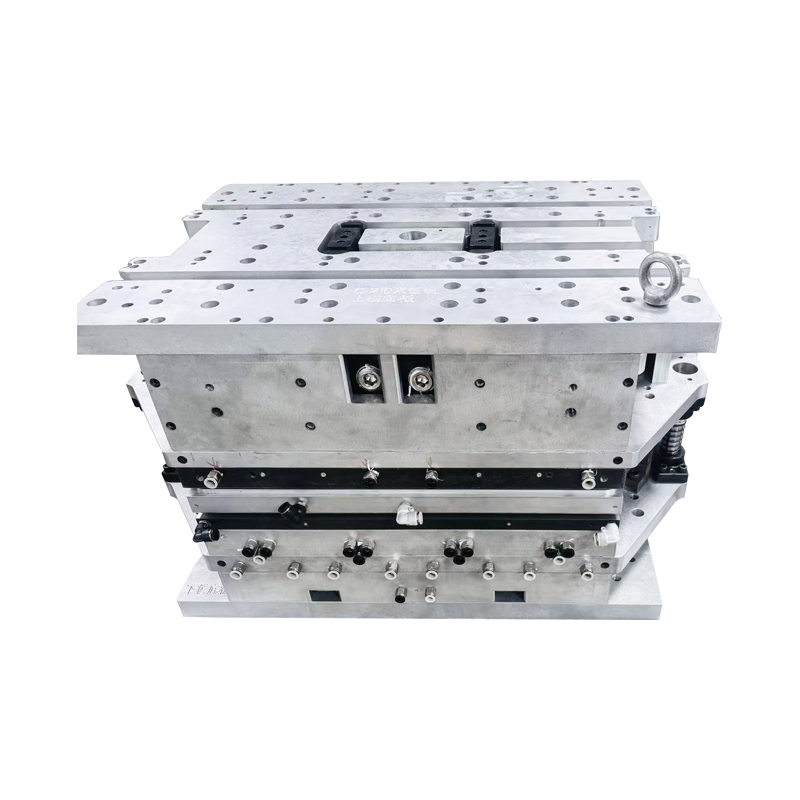
The manufacturing of modern high-speed packaging production assets demands absolute precision during the engineering phase. Traditional methodologies that relied on two-dimensional layouts and empirical trial-and-error modifications are no longer viable in an industry focused on cycle-time minimization and material optimization. High-volume production of thin-gauge packaging requires specialized lunch box thermoforming mold assemblies designed to withstand continuous pneumatic and mechanical cyclic loading while maintaining uniform thermal dissipation properties across all tool cavities.
Integrating modern cad design software directly into the tool-and-die drafting workflow enables processing facilities to model complex three-dimensional draft angles, calculate material draw ratios accurately, and simulate real-world physical stresses before a single piece of tool steel or aluminum alloy enters a CNC machining center. By shifting verification upstream into digital environments, toolmakers can mitigate expensive geometric deviations and ensure flawless high-volume operation.
Technical Note: Industrial thermoforming operates within narrow processing windows. Minor geometric inconsistencies within mold pockets can lead to localized wall thinning, structural buckling, and erratic stacking configurations during automated downstream packaging operations.
2. Core Technical Capabilities of 3D Modeling Software
The implementation of premium 3d cad design software changes how mechanical engineers approach complex multi-cavity tool geometries. Advanced surface modeling functions within modern software allow design teams to construct organic, ergonomic contours that optimize plastic material distribution while maintaining required volumetric capacities. When developing multicavity food packaging tools, parametric modeling engines ensure that modifications made to a primary master cavity propagate instantly throughout the entire multi-station layout.
Parametric Feature Manipulation and Associativity
Parametric design allows engineers to define explicit geometric relationships between separate mold components. For instance, modifying the overall lip thickness of a container profile automatically updates corresponding pocket clearances, pressure box dimensions, and plug assist parameters across the entire layout. This bidirectional associativity drastically cuts down engineering hours during iterative prototyping phases, protecting design integrity across assembly drawings, machining blueprints, and structural analysis files.
Advanced Surface Topology and Continuity
High-performance 3d modeling software provides the mathematical control needed to achieve curvature continuity along complex transition radii. Tool designers leverage precise surface adjustments to prevent abrupt cross-sectional changes that cause stress concentration zones in the thermoformed plastic sheet. This advanced geometric control helps maintain consistent material thickness along deep-draw pocket walls and tight corner radiuses.
3. Comprehensive Mold Core and Cavity Engineering
Developing high-volume thermoforming tooling requires a clear separation between the upper and lower mechanical forming zones. Specialized design workflows, such as SolidWorks mold design, provide dedicated toolsets to extract distinct parting lines, split shut-off surfaces, and separate the raw geometric assembly into dedicated mold core and cavity design architectures. This digital segmentation lets engineers optimize venting configurations, material selections, and specific thermal pathways for both sections of the tool.
The female cavity plates typically define the external aesthetic profile and structural ribbing of the container, while the male core regulates internal dimensional control and provides mechanical plug assistance tracking. Designing these components within a shared CAD assembly ensures perfect alignment during high-speed clamping cycles, eliminating mismatched parting lines and reducing mechanical wear on the forming press guide pins.
Cavity Side Engineering
Focuses on surface finish quality, material branding details, and structural stacking lugs. Requires precise draft angle calculations to ensure clean, automated part ejection without scuffing mechanical surfaces.
Core Side Engineering
Manages internal part tolerances, mechanical stripping rings, and structural material distribution. Typically includes complex venting micro-channels to quickly evacuate trapped air during forming cycles.
A primary challenge in multicavity tooling is managing thermal gradients across large mold plates. Fluid dynamics simulations run within the CAD space let engineers design precise cooling channels that wrap closely around the core and cavity inserts. Maintaining consistent surface temperatures across all cavities is critical to preventing part warping and ensuring stable production output.
4. Implementing Plastic Shrinkage Tolerance Formulas
A common pitfall in tool design is assuming that a mold pocket should exactly match the target dimensions of the final plastic part. In reality, thermoplastic resins shrink substantially as they cool from amorphous forming temperatures down to stable ambient storage states. Engineers must scale tool geometries upward using specific plastic shrinkage tolerance metrics to ensure the final product meets design requirements.
Shrinkage rates depend heavily on material choice, sheet thickness, orientation, and specific tool temperatures. Amorphous polymers like Polyethylene Terephthalate behave differently than semi-crystalline alternatives like Polypropylene, which exhibit higher, directionally dependent shrinkage rates. The table below outlines standard shrinkage factors used by tool designers when setting up CAD scaling parameters.
| Polymer Class | Common Materials | Average Shrinkage Range | Tool Scaling Factor |
|---|---|---|---|
| Amorphous | PET / APET | 0.4 percent to 0.7 percent | 1.005 |
| Semi-Crystalline | PP (Homopolymer) | 1.5 percent to 2.2 percent | 1.018 |
| Impact Modified | HIPS | 0.5 percent to 0.8 percent | 1.006 |
| Bio-Based | PLA | 0.3 percent to 0.5 percent | 1.004 |
Applying these scaling values requires a deep understanding of part geometry. Deep-draw designs often experience non-uniform shrinkage, with more pronounced movement along the primary material draw direction compared to transverse axes. Advanced 3D CAD platforms let design teams apply non-uniform, anisotropic scaling factors along independent coordinate vectors to counter this behavior and prevent part distortion.
5. Decoding GD&T for High-Precision Toolmaking
Traditional plus-minus dimensioning often falls short when validating complex, multi-cavity thermoforming machinery. Geometric dimensioning and tolerancing provides a standardized mathematical language to explicitly define the allowable variation of mechanical features based on their functional relationships. Understanding the underlying gd&t meaning is essential for tool designers who must communicate strict manufacturing limits across global supply chains.
Rather than simply bounding a feature between linear limits, GD&T uses a system of explicit geometric control zones. This approach ensures that separate tool components—such as vacuum punch assemblies, perimeter trim steels, and multi-station mold bases—fit and align correctly during high-speed, continuous production runs.
By establishing clear datum reference frames, GD&T allows quality control inspectors to measure tool elements from the same functional baselines used during the initial 3D modeling phases. This alignment reduces measurement ambiguity and helps prevent costly disputes between tool designers and CNC machining centers.
6. Critical Geometric Tolerances in Thermoforming Tooling
When creating a comprehensive tool and die CAD drawing, specific geometric controls are required to guarantee long-term tool performance and mechanical interchangeability. In structural thermoforming layouts, positional accuracy, surface profile controls, and parallelism runouts determine whether a tool operates smoothly or fails prematurely due to mechanical interference.
- Surface Profile Control: Applied to complex container cavities to define a uniform three-dimensional tolerance envelope around the theoretical CAD surface profile. This control ensures consistent internal volumes and reliable automated part nesting.
- Positional Tolerancing: Used to define the precise locations of mechanical guide pin bushings, co-axial vent holes, and support pillar arrangements relative to primary reference datums. This replaces less accurate coordinate tolerance grids.
- Parallelism and Flatness: Critical for large multi-cavity backing plates. If a mold plate lacks proper flatness, clamping forces will distribute unevenly across the tool, causing flash along part edges and accelerating local wear.
- Concentricity and Coaxiality: Applied to critical plug assist rods and matching cavity centerlines to ensure material stretches symmetrically during the initial vacuum forming stages.
7. Optimizing Venting, Cooling, and Material Ejection
Beyond basic part shape, a thermoforming tool must serve as an efficient heat exchanger and pneumatic pressure vessel. High-performance CAD platforms let engineers optimize these functional systems directly within the primary 3D workspace. This digital integration helps ensure production cycles run as quickly and reliably as possible.
Venting System Design
To prevent trapped air pockets from distorting the forming plastic sheet, molds require strategic vacuum venting holes. Using 3D modeling tools, engineers can map out dense patterns of micro-vents along interior corners and deep recesses. These features are sized small enough to prevent plastic material from migrating into the holes and leaving cosmetic defects on the finished parts.
Conformal Cooling Integration
Traditional drilled fluid lines are restricted to straight geometric paths, which often limits cooling efficiency near complex part curves. Modern tool engineering resolves this by utilizing conformal cooling channels. Designed within CAD and built using advanced additive or multi-piece CNC techniques, these channels mirror the exact topology of the mold cavity. This uniform cooling minimizes internal part stresses and reduces overall cycle times.
8. Troubleshooting Common Tooling and Defect Vectors
When production defects surface during mid-to-high-volume thermoforming operations, the root cause can often be traced back to geometric issues or tolerance stack-ups within the tool assembly. Addressing these errors during the initial digital design phase is far more cost-effective than modifying hardened tool steel after a production line halts.
| Observed Defect Type | Root Tooling Factor | CAD Optimization Strategy |
|---|---|---|
| Localized Wall Thinning | Insufficient transition radii | Apply curvature continuity rules to smooth deep-draw corners. |
| Part Deformation / Warp | Uneven cooling channel layout | Redesign cooling geometries using conformal thermal simulation data. |
| Ejection Scuff Marks | Inadequate draft angles | Increase vertical wall draft clearance within the parametric model. |
| Flashing Along Trim Lines | Poor plate flatness tolerances | Tighten flatness and parallelism specifications across bolster plates. |
By combining advanced mechanical analysis tools with strict geometric controls, engineering teams can predict and eliminate these common processing defects. This digital optimization step ensures the final production tools deliver reliable, high-volume performance right from the initial startup phase.
9. Summary of Engineering Best Practices for Mold Production
Successfully engineering high-precision thermoforming molds requires a careful balance of advanced software design, proper material scaling, and rigorous geometric dimensioning. By establishing structured design workflows, manufacturing facilities can consistently deliver tooling that meets strict performance and durability standards.
Key Engineering Checklist:
- Always apply anisotropic shrinkage factors based on the specific thermoplastic material and draw ratios used.
- Use a comprehensive datum system within GD&T to control part variations across multi-cavity tool plates.
- Integrate detailed thermal and fluid simulations early in the design process to optimize cooling efficiency and minimize part warping.
- Maintain clear, centralized parametric data models to ensure updates propagate reliably across all core, cavity, and component drawings.
10. Frequently Asked Questions
Q1: How does 3D CAD design software calculate shrinkage differences between materials like PP and PET?
Engineers manually input specific volumetric expansion coefficients into the software scaling engine. Because semi-crystalline materials like PP shrink more than amorphous polymers like PET, the original mold cavities within the CAD layout must be scaled up non-uniformly to compensate for these distinct physical properties before machining begins.
Q2: Why is the definition of GD&T meaning so critical for multi-cavity thermoforming toolbases?
GD&T defines precise, three-dimensional tolerance zones instead of traditional linear limits. This is crucial for multi-cavity tools because it prevents small alignment errors from accumulating across the mold plate. Proper geometric controls ensure every cavity aligns perfectly with matching plug assists and punch-trim dies during rapid machine cycles.
Q3: Can a standard tool and die CAD drawing be transferred directly into CAM systems?
Yes. Modern parametric design platforms offer direct compatibility with computer-aided manufacturing software. This integration allows CNC programmers to generate precise toolpaths directly from the solid geometry, minimizing manual transcription errors and ensuring the finished steel matches the approved digital design.
Q4: What draft angle is typically recommended for deep-draw container mold cavities?
A minimum draft angle of 1 to 2 degrees per side is generally required for standard thermoforming cavities. For deeper draws or textured surfaces, increasing the draft up to 3 to 5 degrees may be necessary to ensure clean part ejection and prevent cosmetic scuff marks during automated handling cycles.